Pi Augmented Reality
Tommy Chen & Rhia Malhotra
tc575 rm722
Spring 2023
Demo video of the project in action
Objective
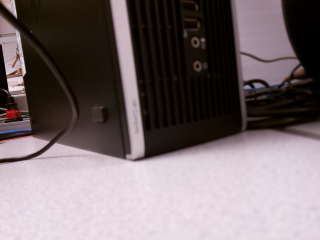
The Raspberry Pi 4 Augmented Reality project aims to display on a TFT panel rendered objects overlaid on a video feed taken from the PiCamera module. User interactivity is accomplished through the use of a MPU6050 module that adjusts the rendered view in real-time based on movement of the Pi system.
Introduction
For this project, we really wanted to make something portable embedded-system-like. To that end, using just a TFT screen, camera, and a six-axis sensor, we made a display that takes in a camera feed and overlays a rendered object on top of it using the ImageMagick command-line toolset. By moving the system around, the program takes in current accelerometer and gyroscope readings to update the position of the object based on the original position. The display is then updated with the new render, thus giving us a sort of small-scale augmented reality. In order to show the camera feed underneath the objects, we modified preexisting renderer code to support background transparency. Camera images were taken using Raspistill, and the most recent version of the now-deprecated WiringPi was used to get raw data from the MPU6050 module.
Design & Testing
We began by reverting the Linux kernel on our SD card to the one used in Lab 3 (Bullseye), because we weren’t sure how the PreemptRT kernel patch would affect the rest of our code.
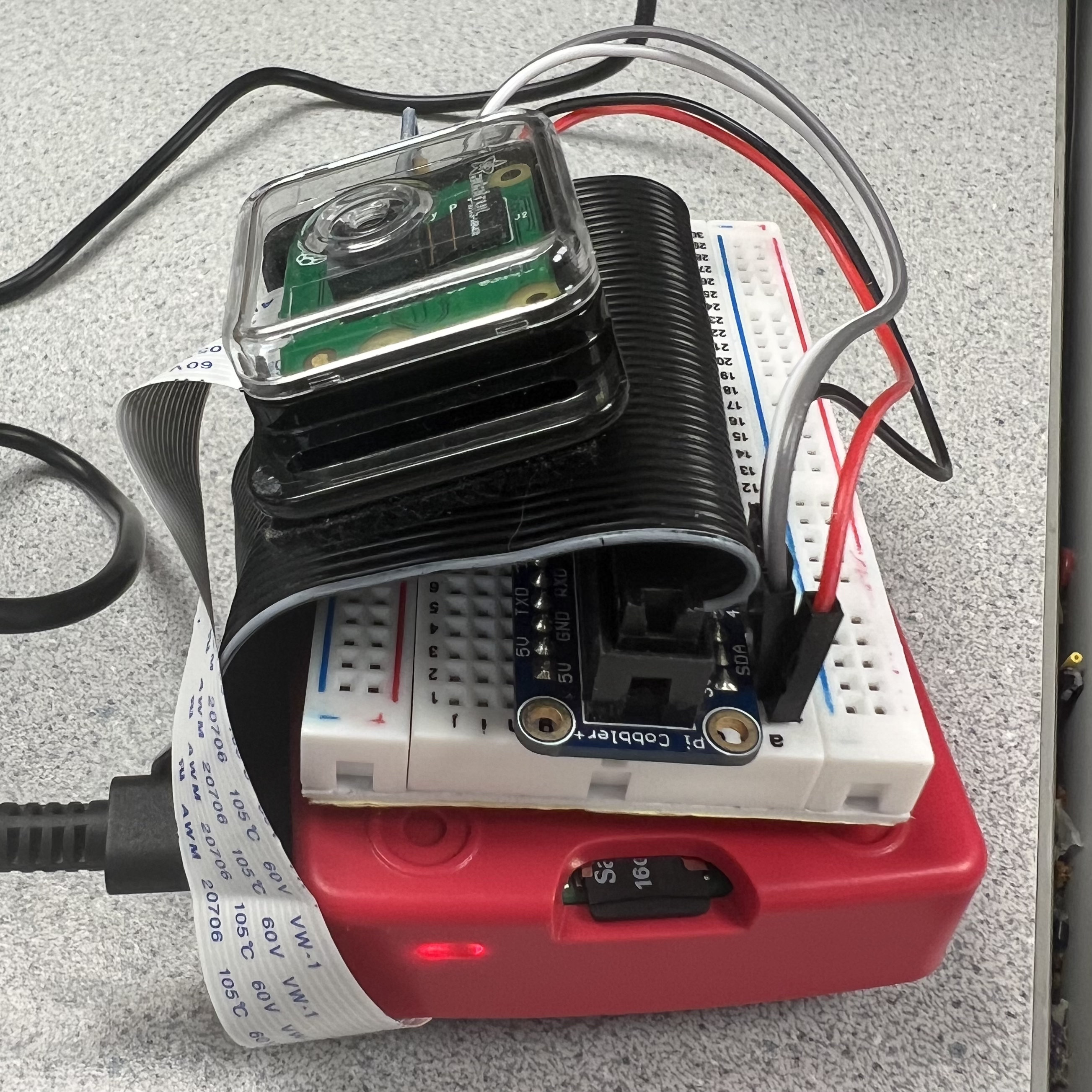
We connected the embedded components for the project to the Raspberry Pi, and tested how well they worked. The MPU 6050 accelerometer was soldered to a header so it could be linked to the Raspberry Pi via a breadboard. We intended to control the MPU6050 via the WiringPi software library. This was difficult to do because the library maintainer for WiringPi stopped working on it and the download source was cut off. We had to spend time finding the most recent mirror for the library. After installation of the Wiring Pi library mirror, we ran public source code (which used Wiring Pi) for reading out MPU6050 acceleration and gyroscope measurements. We confirmed the code worked by rotating and translating the accelerometer and Pi along different axes. The accelerometer readings needed calibration but were workable.
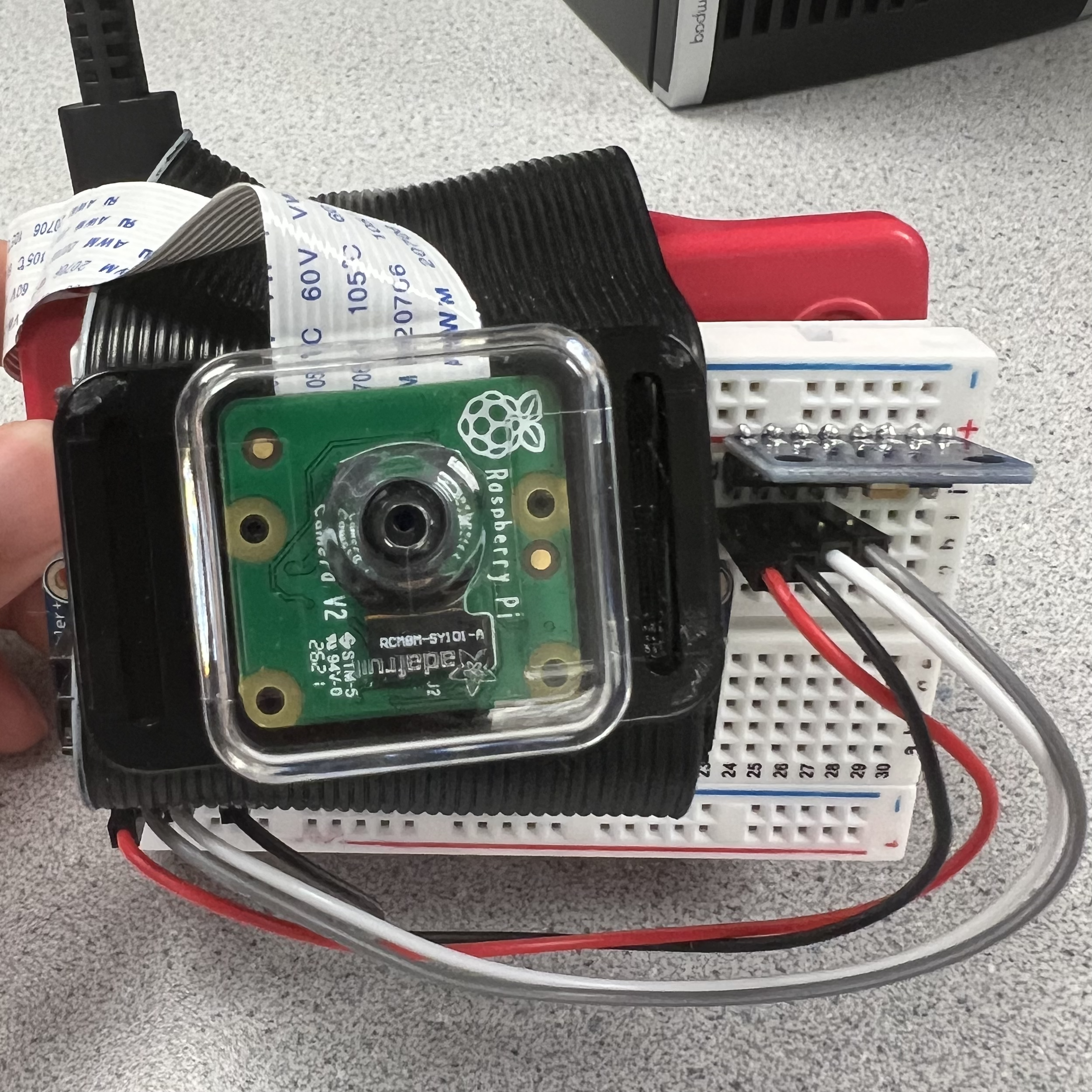
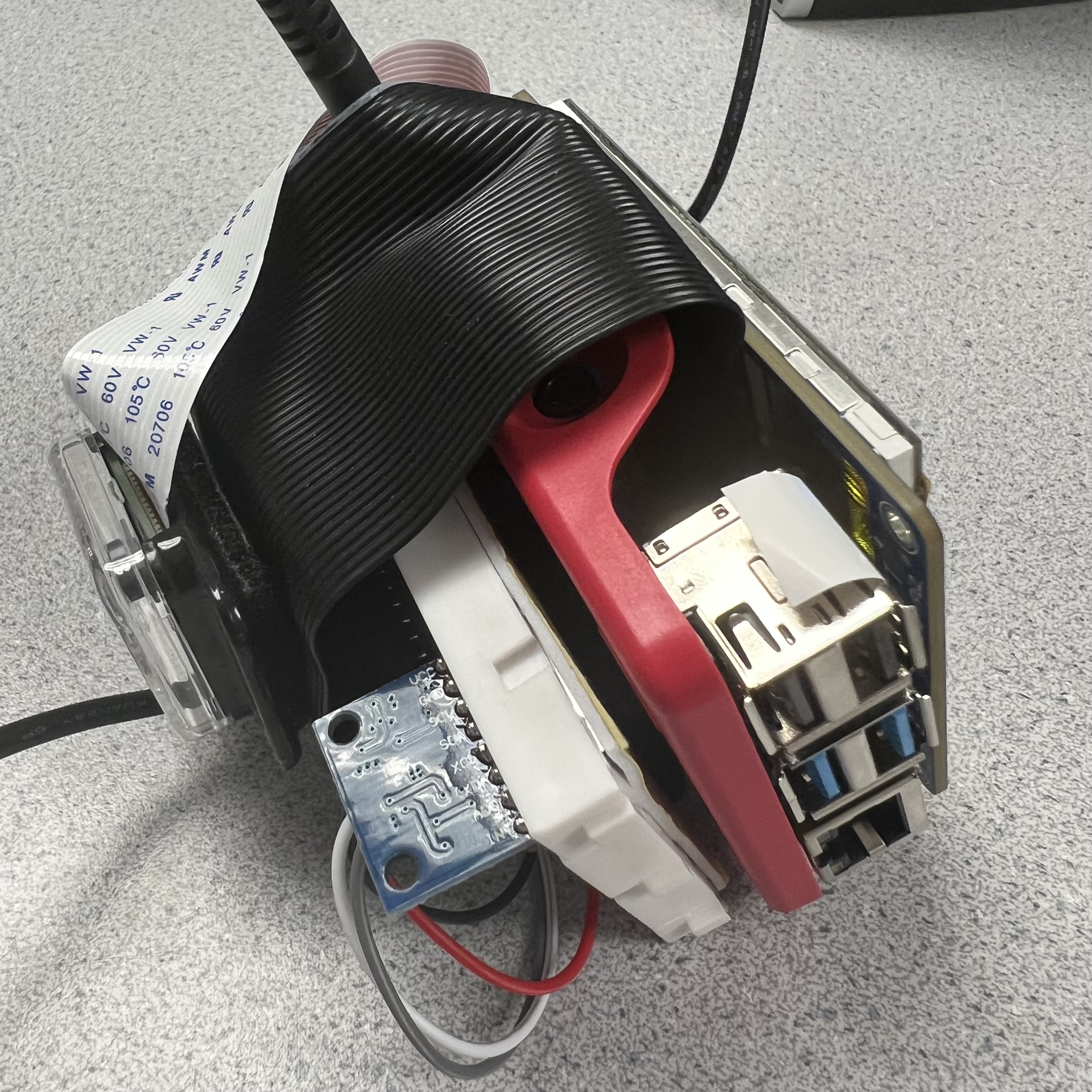
The TFT was already connected to the Raspberry Pi via the breadboard, so the only other embedded component left to connect was the RaspiCam. We velcro-ed this to the ribbon cable attaching the TFT to the Pi, and wired it to the breadboard. The camera module was connected via included cable to the camera slot on the Pi. The public RaspiVid library was used to control the camera. To test the camera and the library, we began with simple commands to take and display camera stills. With code from Lab 1, we piped RaspiVid commands into the mplayer, so the camera view displayed on the TFT. Once we confirmed the camera and library worked together this way, we tried live streaming the camera view. Initially, the livestream had a buffer of about 30 seconds, but we noticed the buffer decreased as time went on. We identified the cache was causing the buffer. By digging around some hobbyist blog posts, we found that making the mplayer play the video at a higher framerate than the video created by the RaspiVid command forces it to play the video at a high speed until it reaches the end of the buffer time. This quickly reduced our buffer to a near-real time live stream.
After the embedded components were all connected to the Raspberry Pi, we focused on rendering images on the TFT. We realized that overlaying rendered images on top of a livestream could be done more easily by taking in a camera image PNG, overlaying a rendered object on the png, and outputting a new image. We moved from “true live streaming” to quickly taking in camera images and displaying edited images to the TFT.
We followed an online ray tracing tutorial in C++ to render a basic gradient on the TFT. Initially, we had intended to follow just the one tutorial to render objects of our choice on the screen. However, neither of us had much experience with C++, and we quickly realized we would work better implementing the ray tracing math using structs in C as opposed to classes in C++. We dug around and found someone who had implemented the entire ray tracing tutorial in C, with public GitHub code. However, the objects we wanted to render were much simpler than what they had created, and they did not show any intermediate steps in following the ray tracing tutorial. We downloaded the code and spent a week or so deciphering it and experimenting with parameters until we were able to render a sphere on the TFT screen.
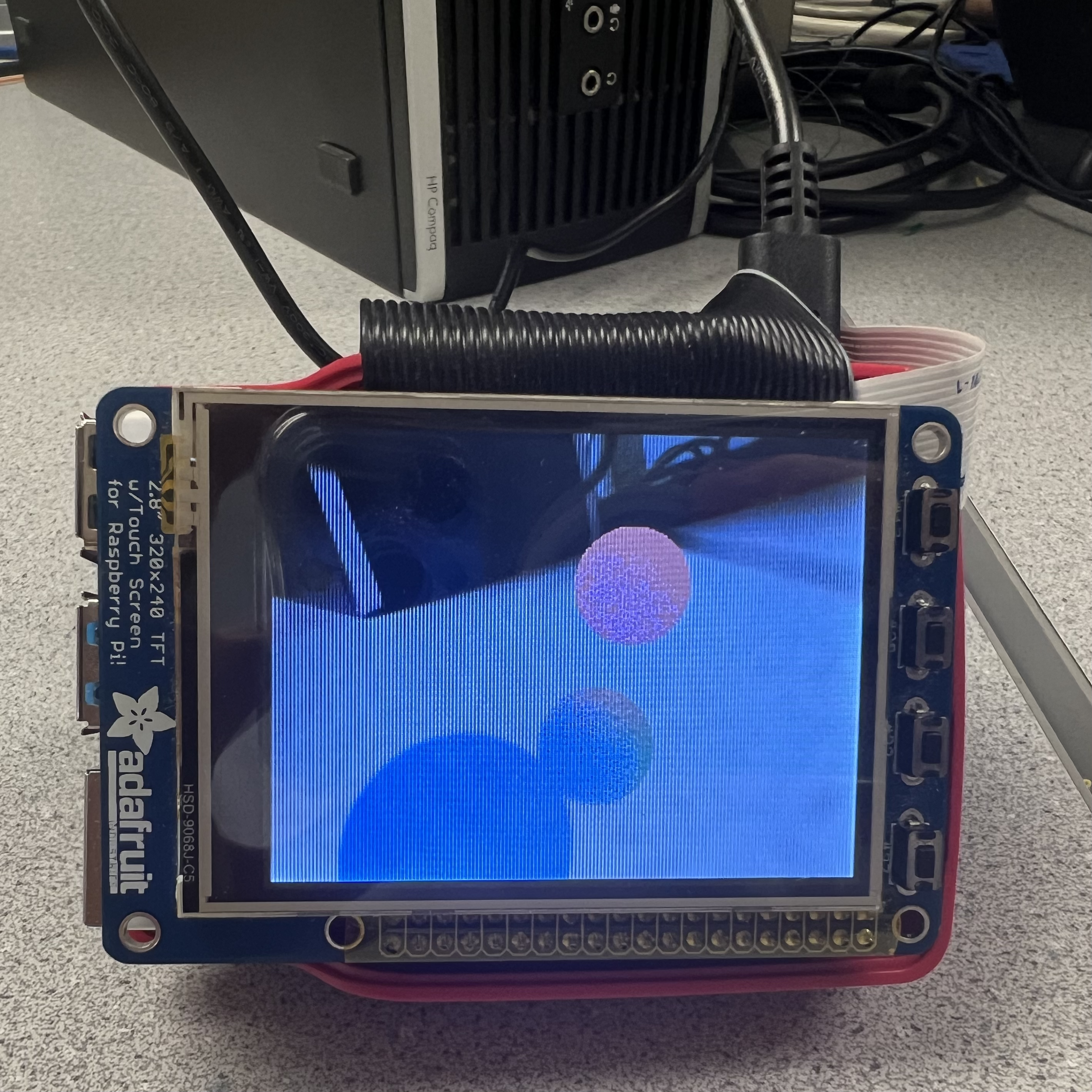
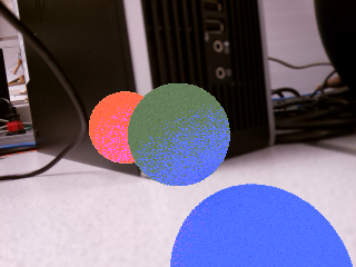
Because we want to create an augmented reality experience, we need to overlay objects with no background onto a visual of the user’s surroundings. After rendering a sphere on the TFT, we worked on removing the background, floor, and simulated external light sources from the render. This again required much experimentation, stepping through different parts of the code and rereading variable definitions and instantiations. Eventually, we were able to remove the floor and background from the rendered image, but we still had a white outline around the object. We solved this by setting all pixels with the same color as the background as transparent. With better understanding of how the ray tracing render works, we moved to rendering multiple objects (three spheres) on the screen instead of one. Testing for this was done by repeatedly rendering stills on the TFT.
With the render and the accelerometer working individually, we sought to link them together such that real-time accelerometer readings adjusted the viewing angle of the rendered object. Initially, we thought the way to do this was by calculating the accelerometer’s angles of rotation relative to itself: roll, pitch, and yaw. We even imported a C++ library and compiled it with C code to calculate the roll, pitch, and yaw. However, the MPU6050 suffers from gyroscopic drift that only gets worse with time. Additionally, there seemed to be some issues with merging the C code that used the C++ MPU 6050 library with the rendering code. We ended up scrapping the idea of using roll, pitch, and yaw in favor of reading in and calibrating acceleration and gyroscope measurements.
To better understand how the field of view of the rendered object works, we changed the viewing angle of the render, incrementing it by 15 degrees every second, and seeing how that affected the image displayed on the TFT. We noticed that when the viewing angle was rotated 180 degrees, the image reflected along the x and y axis. We hardcoded a check in the code to flip the image back to where it should be after this. Once we were able to render a 360 degree rotation around the virtual object, we moved on to linking adding in the accelerometer and gyroscope code.
The MPU6050 upon startup has displaced acceleration and gyroscope measurements that are nonzero when they should be zero. We took the initial measurements of the MPU6050 on startup and used them as offsets to “calibrate” future acceleration and gyroscope readings. The acceleration measurements were used to “translate” the field of view of the camera whereas the gyroscope measurements were used to “rotate” the camera field of view about the object at each time step. We scaled the calibrated measurements before putting them into the rendering code to update the field of view. Testing for this was done by running the linked up rendering and accelerometer code and observing the TFT view while rotating and translating the camera in space.
Results
We were able to accomplish the base goals for this project, but did not get much of a chance to tackle the stretch goals. There is still noticeable lag in the rendering speed as well as instability in the calculations using data from the six axis sensor. We were able to get a stable image when the Pi is held still, but the render’s reaction to movement isn’t as smooth and responsive as we would have liked. However, we are happy with the quality of the render itself. Even by reducing the number of samples per render to 8 (down from 64), the program still produced a decent image when viewed on the TFT every two seconds or so. Though we switched to capturing and displaying still images every rendering loop, we did initially consider layering renders on top of a video feed instead. The decision to switch to still images was due to the commands we wanted to use from ImageMagick. We were able to combat sensor drift to an extent, but to get better real-time performance we think it would require a lot of changes to the main program loop to better sync up all the components (for example, we take one positional reading before the render, which means that any movement afterwards is not captured until the next render starts).

Conclusions
A large portion of the time spent on this project was dedicated to digging through code and library documentation to figure out what we needed to modify to get things to work. Rather than writing code from scratch, we thought it would be easier to find base code to work with, but it ended up being both a blessing and a curse. On one hand, it let us quickly get various prototypes working, but it also had too much functionality that we weren’t interested in, bloating the code a little. We hope the modifications and comments we made on the code as we went through them will help anyone looking to play around with our project files. Because we wanted to see how far we could get with the Raspberry Pi performance-wise, we chose to use rendering as our way of displaying objects on the TFT. However, this could be replaced with a 3D model, saving a lot of processing time that could then be dedicated to adding shadows and effects. Compared to previous projects we have worked on, this project was a new experience in cobbling many different programs and libraries together to get something working, rather than doing everything from scratch.
Future Work
Some of the libraries / programs we used for the project have newer options available, but we stuck with the older versions so that finding documentation and debugging would be a little easier. However, in the future, these could be updated. Instead of raspistill, libcamera seems to be the newer version for the camera module. Additionally, WiringPi is now deprecated, so it would be good to find a different library for MPU6050 communication. Some of our stretch goals that we did not get to implement were: making use of the TFT touch screen for more user interaction, adding render effect options, changing the objects in the render, etc. We would have also liked to put more work into optimizing the render and reducing the latency between frames.
Parts List
Raspberry Pi 4 Model B $50.00Raspberry Pi Camera V2 $30.00
HiLetgo GY-521 MPU-6050 $7
Half Sized Breadboard $5
Wires, Velcro, Extension Cable $10
Total: $102
Tips & Tricks
To get the live camera feed working as mentioned above, the command we ran was:
raspivid --width 320 --height 240 --bitrate 1000000 -fps 25 -t 99999999 -o - | mplayer -fps 40 -cache 1024 -
Note how the recording is done at 25 fps but the playback is done at 40 fps. This depletes mplayer’s video buffer, making it instantly display the current video stream being piped in. We tried to play around with disabling the buffer / decreasing the size, but did not get very far. This command takes around 30 seconds before the buffer depletes.
To add transparency support to the image writer, the number of channels needs to be increased to 4 instead of 3. This also requires modifying the size of the data array as well as the array indexing so that every fourth index is now the transparency value for that pixel. We used the PNG file format because some other formats do not support transparency.
For future tinkering with the rendering code, note the importance of the “Up vector” which can end up flipping the rendered image on either or both axes. This problem occurs when you try to position the camera to the back, past the half-sphere of view centered at the look-at point. This can be remedied through a series of bounds checks on the camera position vector, and updating the Up vector.
Work Distribution
Tommy
tc575@cornell.edu
- Library integration
- Transparency modifications
- Terminal commands with ImageMagick
- General program workflow
Rhia
rm722@cornell.edu
- RaspiCam display testing
- Accelerometer readings and calibration
- Importing and compiling C++ accelerometer library (scrapped)
- merging accelerometer and ray tracing code